Ionising radiation had a strong disturbing effect on the performance of the
detectors. The high flux of protons and electrons trapped in the Earth's
radiation belts made operations impossible. At about ![]() after perigee
passage the temporary radiation damages of the detectors were cured by a
combination of heating, flashing and bias increase (see
Section 4.2.5). Outside the radiation belts, during the
16 hour science window, the ionising radiation remained a limiting factor
to detector performance. Not only direct hits on the detector, but also
secondary electrons released by satellite materials after a hit caused
disturbances.
after perigee
passage the temporary radiation damages of the detectors were cured by a
combination of heating, flashing and bias increase (see
Section 4.2.5). Outside the radiation belts, during the
16 hour science window, the ionising radiation remained a limiting factor
to detector performance. Not only direct hits on the detector, but also
secondary electrons released by satellite materials after a hit caused
disturbances.

|
Primary, ionising radiation consisted of high energy protons and heavier nuclei. It caused several effects in the photoconducting detectors:
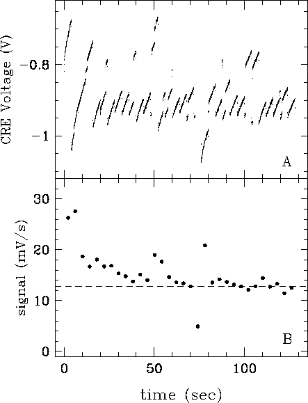
A glitch can be recognised by a step on the integration ramp between two readouts. The influence of low level glitches to low signal data is illustrated in Figure 4.6.
Note that the energy of the particle passing through the detector is not directly correlated with the (measured) glitch energy. The glitch energy depends on the number of electrons freed by the high energy particle along its path through the detector. Higher energy glitches can cause ramps to saturate or can even cause a transient for several seconds. Low level glitches become more apparent in measurements with low in-band power. Examples are faint sources on a low background, PHT-S spectra of faint targets, observations with small apertures using detectors P1 or P2.
The glitch rate is a function of the detector size and the energy deposited. Calibration measurements were carried out to determine the particle hit rate as well as the signature of the glitches as a function of orbital position of the satellite with respect to perigee passage. On average, a clear glitch is detected every 10 s for standard science observations.

|
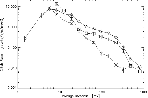
Analyses of glitches have shown that they have a continuous energy distribution (Figure 4.7). Detectors P3 and C100 were more vulnerable to cosmic rays. These detectors exhibited a temporary responsivity variation for several seconds. Although special algorithms have been developed to remove these disturbances, they can determine the sensitivity limit of these channels.
The slow responsivity increase caused by cosmic rays in the 16 hour science window is about 20% for the silicon doped detectors P1, P2 and PHT-S. It can reach a factor 2 for the P3 and C200 detectors. These variations are calibrated out by FCS reference measurements which are equally affected as the celestial targets in the same observation sequence. Moreover, to minimize the disturbance, an extra curing procedure was introduced for the detectors P3, C100 and C200 to be carried out near apogee, when the satellite was handed over between the two ground stations.
The radiation effects described here became worse during periods of higher solar activity. Also measurements carried out near the end of the science window, when ISO was approaching the radiation belts, suffered from increased radiation effects.
The tuning of the parameters controlling the OLP deglitching algorithms has been performed empirically after evaluation of many datasets. Descriptions of the algorithms are presented in Section 7.3.4.