

Next: 4.3 Glitches
Up: 4. Calibration and Performance
Previous: 4.1 Responsivity
Subsections
4.2 Dark Current
With the term `dark current' we indicate the level of the signal measured
when the detector is in darkness, i.e. when no external flux reaches the
detector. Strictly speaking, this is not a current, but an electronic
reference level including both real dark current and electrical offsets.
4.2.1 Dark level (SW)
With the camera closed, the charge generation in the SW detectors was
not due to thermal effects, but to quantum tunneling effects. It
increased slowly with the logarithm of on-chip integration time. Thus
very long integration times were possible without running into
serious dark current accumulation problems. The dark current level
and the detector noise just after launch were the same as during the
ground tests, and stayed very stable for the whole duration of the
mission, with the exception of a small increase in the noise (about
2.5%) after revolution 700 (Boulade & Gallais 2000,
[14]).
Darks obtained from calibration measurements are included in the CGSWDARK
calibration file described in Section 6.1.2. The dark
currents provided in the calibration file are estimated to be accurate to
about 0.5 ADU/G/s (Biviano et al. 1998a, [5]).
4.2.2 Dark level (LW)
The dark level of the LW array arose as the sum of 2 effects, a leakage
of charges
generated during the commutation of the reset transistor,
and thermal charge generation in the photoconductors.
The first effect was dominant for on-chip integration times up to 10
seconds.
For longer integration times, charge generation was dominant.
The dark frame pattern exhibits a strong line
effect with a separation between odd and even lines as can be seen in
Figure 4.3.
Figure 4.3:
An example of the LW dark frame, measured
with 2.1 seconds on-chip integration time. Note the very evident
line pattern.
|
|
During in-orbit operations an extensive campaign was performed to study the
dark current behaviour. A description of the data and the analysis
performed can be found in Biviano et al. 1998a, [5];
2000, [9] and Román & Ott 1999,
[50].
Three type of significant drifts of the LW dark current were found:
- a short term drift, i.e. a modification of the dark current
within a single revolution, from the beginning of the revolution to the
end; this drift was in general non-linear, and it was
different for different pixels and integration times;
- a long term drift, i.e. a linear decrease of dark current
from a revolution to another, with a typical time scale of days; this
drift was also found to be different for different pixels and integraton
times;
- a correlation of the dark current with the temperature of the ISOCAM
focal plane which follows a linear relation and is the same for all
pixels and for all integration times.
The impact of each of these effects can be summarized as follows:
- short term: the drift within each revolution was

 0.5 ADU from the activation to the de-activation of
the instrument;
- long term: the drift was

 ADU from the
beginning to the end of the ISO mission;
- temperature dependence:

 0.25 ADU over the full
range of temperature variation (few hundreths of a Kelvin).
Consequently, a model was developed that takes the different dependencies
found into account and corrects the observed LW dark current per pixel
as a function of the orbital position of the spacecraft and the
temperature of the ISOCAM detector. The parameters
of this model are provided in the CCGLWDMOD-file
(Section 6.1.3). Once the corrections are applied, the
median LW dark current residual amounts to  0.25 ADU
(Biviano et al. 2000, [9]).
No similar trend was found for the SW channel.
Figure 4.4:
The mean signal (top) and noise (bottom) level
of the 2.1 seconds on-chip integration time handover LW dark
current measurements
during the ISO lifetime.
|
|
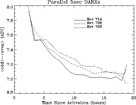
Figure 4.5:
The (median-filtered) difference of the
mean dark currents of the odd and even line pixels of the LW detector.
We show measurements, as a function of time since instrument activation,
for 5 seconds on-chip integration time in ISOCAM parallel mode, during
three ISO revolutions.
No correction for the long term trend has been
applied to the data so that a shift is visible from revolution to
revolution.
|
|
To demonstrate the long term trend we show in
Figure 4.4 the behaviour of
the mean signal (top) and noise (bottom) level of the 2.1 seconds on-chip
integration time handover LW dark current measurements
(Section 3.7.4) through the ISO lifetime
(Gallais & Boulade 1998, [35]). One immediately
notes a decrease
of the dark current throughout the mission. A more careful inspection
demonstrates that the dark pattern on the array changed, the
behaviour of odd and even lines being different.
The short term trend in the dark level, i.e. the dark current as a
function of orbital position or, in effect, as a function of the time since
activation of ISOCAM, is shown in Figure 4.5. Note the
very similar trend in the difference between odd and even lines of the
LW detector. The example is given for three revolutions with the
5 seconds on-chip integration time. For other examples see
Biviano et al. 1998a, [5].


Next: 4.3 Glitches
Up: 4. Calibration and Performance
Previous: 4.1 Responsivity
ISO Handbook Volume II (CAM), Version 2.0, SAI/1999-057/Dc


![\resizebox {13cm}{!}{\includegraphics*[54,537][415,775]{hand_dark_lw2.ps}}](img101.gif)
