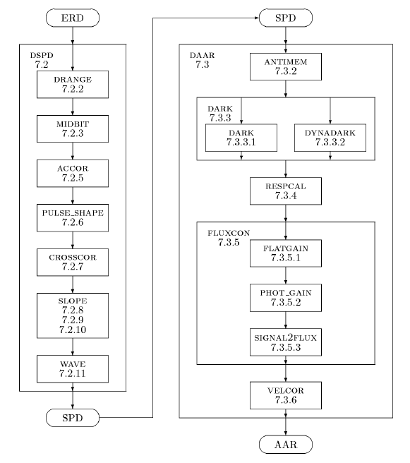
The software of the SWS pipeline Version 10.1 is written completely in IDL. Figure 7.14 presents an overview of the OLP software. There are two global procedures: DSPD which processes and ERD into an SPD and DAAR which takes the SPD and yields an AAR. Each of these processes can be subdivided into other processes as shown in Figure 7.14. Although the SWS pipeline itself does not benefit from this setup, it made it possible to recreate the pipeline and all its constituent parts within OSIA. Each of the parts of the pipeline can be called within OSIA by the names shown in Figure 7.14 and if wished some may be replaced by other more interactive procedures or different calibration files may be connected. E.g. RESPCAL might be replaced by RESP_INTER to get a better handle on the residual fringes in bands 2 and 3.

In the pipeline and OSIA v3 the errors are implemented in three separate parts,
one statistical error and two systematic errors. The statistical error is just
the stdev of the slope, found in SWSPSTDV or
SWAASTDV, see Sections A.3.1 and
A.4.1. This stdev tag is completely uncalibrated, still in
![]() V/s. We decided to leave it like this to keep the option to use this
stdev
as weight in later processing, or to use it for histogram clipping based
on the stdev in e.g. low signal processing.
V/s. We decided to leave it like this to keep the option to use this
stdev
as weight in later processing, or to use it for histogram clipping based
on the stdev in e.g. low signal processing.
As the decision to keep three kinds of errors was taken quite late in the mission, we had to find room for the two systematic errors. So we (mis)used two spare tags in the AAR for it, both of which were only 1 byte long. So we had to devise some encoding for the offset and gain error. See Section 7.5.2.
In the pipeline the offset error is not completely right according to what is
written here, whereas in OSIA v3 it is. Within OSIA there is a routine
(DECODE_AA_ERROR) to decode the systematic errors and calibrate
the stdev tags. It also yields a structure which contains the calibrated errors
plus the total error
![]() as in Equation 7.15.
as in Equation 7.15.
Within the AAR there are two spare tags which are used to store error information: SWAASPAR[1] contains the gain error in % ranging from 0 to 255 and SWAASPAR[0] contains the value of the offset error in Jy using the lookup Table 7.5.2.
For convenient decoding of errors it is possible to use DECODE_AA_ERROR of the SWS IA system or OSIA.
| parameter | offset | generating |
| value | error | function |
| 0 | 0.0 | 0.1 * value |
| 1 | 0.1 | |
| ... | ... | |
| 10 | 1.0 | |
| 11 | 2.0 | value - 9 |
| 12 | 3.0 | |
| ... | ... | |
| 109 | 100.0 | |
| 110 | 110.0 | 10 * ( value - 109 ) + 100 |
| 111 | 120.0 | |
| 112 | 130.0 | |
| ... | ... | |
| 199 | 1000.0 | |
| 200 | 1200.0 | 200 * ( value - 199 ) + 1000 |
| 201 | 1400.0 | |
| ... | ... | |
| 255 | 11200.0 | MAX value |