|
The instrumental profile intrinsically provided by the grating section of SWS is correctly reproduced in observations done with the SWS02s and SWS06s (and grating observations in SWS07s if such were requested). For SWS01s, grating motions during a detector reset interval are used to speed up execution. These lead to a degradation compared to SWS' physical resolving power. Resolution and other instrumental profile characteristics achieved with SWS are outlined in this section and are reviewed in more detail in the documents by Lutz, Feuchtgruber & Morfill 2000, [29], for SWS02 and SWS06 and by Lorente 1998, [28], for SWS01.
It should be emphasized that resolution values quoted here refer to the resolution as measured by Gaussian fits to the AAR `dot cloud'. However, essentially all SWS data reduction recipes involve a step of `rebinning' or `convolution' aiming at collapsing the dot cloud into a single valued spectrum. Necessarily, this has an effect on the resolution measured in the final spectrum whose magnitude sensitively depends on the chosen parameters and easily reaches 10% or more. Since, for good reasons, different routines and widely varying parameters are chosen, by different users and for different projects, no general `resolution' can be quoted for a rebinned spectrum. Users who need to base their analysis on accurate linewidths from rebinned spectra should estimate this effect themselves for the exact parameter combination adopted in their data reduction.
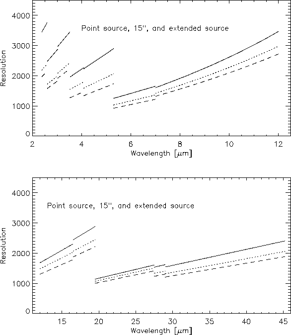
The SWS grating mode spectral resolution is a function of wavelength as well as source size. Figure 4.1 shows the resolution for several source sizes, as derived from an empirical model based on a large set of observations in the ISO database. It is estimated that this model fits the true SWS resolution to an accuracy of about 10%.

|
The SWS Instrumental Profiles are close to Gaussian in shape from the peak down to 5% of the peak height. The most significant deviations are faint blue wings at the few % level in band 3 which are most likely due to an optical effect in the instrument. Band 2 and more clearly band 4 bright lines have faint (few % level) wings on both sides that can be traced to detector transient effects in the up- and down-scans. The FWHM resolution is effectively unchanged by these transients. No `ghost' lines have been observed near bright lines.

|
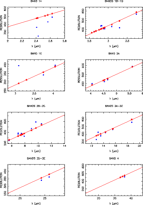
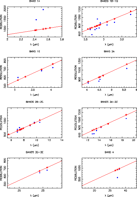
The document of Lorente 1998, [28], gives observed and modelled resolving powers, and simulated line profiles for the four observing speeds of SWS01. Modelling of SWS01 line profiles is more complex than a simple convolution in the spectral domain because the pipeline fits straight lines to the detector integration ramps, even if they are curved because a line was crossed during an SWS01 reset interval. Figures 4.2 to 4.5 show measured and modelled resolutions for the various SWS01 speeds and the various bands. Note that some of the measured lines are very faint, giving outlying resolution values. Table 3.1 (Chapter 3) gives approximate values for the SWS01 pipeline resolution degradation, i.e. the factor by which the resolution of the spectrometer is degraded for SWS01 data processed by the pipeline. The SWS01 line profiles are noticeably non-Gaussian, but their FWHM is always within 10% of the FWHM to a Gaussian fit.

|

|

|
The Fabry-Pérot spectral resolution was measured in laboratory tests at a few discrete wavelengths using solid state laser sources. Figure 4.6 shows the spectral resolution as a function of wavelength, interpolated between these measurements. The spectral resolution decreases towards the short wavelength ends of the wavelength ranges covered by the two Fabry-Pérots, where the wavelengths corresponding to the resonances of the reflective meshes are approached. The Fabry-Pérot spectral resolution depends on precisely parallel FP plates.
Measurements of the Fabry-Pérot spectral resolution in-orbit suffered from the lack of bright, narrow lines. Three lines were measured and lower limits found to the spectral resolution that were very close to expectations. This is reported in Valentijn et al. 1996, [37]. The lower limits are plotted in Figure 4.6.

|
The coordination between Fabry-Pérot scans and the movement of the grating that tracks the FP scan is a source of signature (or, loosely, `noise') that ultimately limits the quality of FP spectra on bright sources. For all but very short FP scans, the wavelength sampled by the FP would soon be no longer tuned to the transmission peak of the grating if there were no tracking. The discrete steps of the grating's tracking movement result in the final FP scan of a pure continuum source looking like a repetition of a small section of the grating instrumental profile.
The amplitude of this `noise' depends on various factors like quality of grating wavelength calibration, ratio between grating stepsize and line profile FWHM, or pointing stability. It is hence difficult to predict for an observation at a certain wavelength. Instrument level tests with optimised grating wavelength calibration showed `signal-to-noise' ratios of around 200. In the case of an observation of a single line on a smooth continuum, part of the `noise' could be calibrated out by observing a larger region of continuum around the line, provided the non-systematic contribution of pointing jitter is not too large.