|
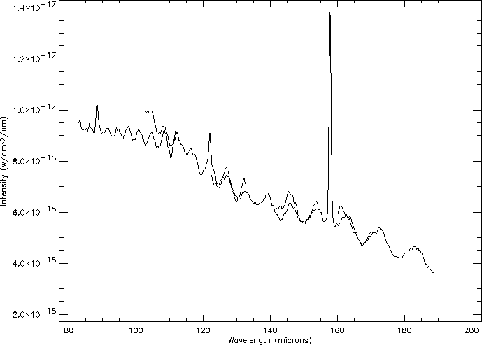
Channel fringes are seen on all LWS spectra of extended or off-axis point sources, as is illustrated in Figure 6.2.

|
Extensive modelling of the response of the instrument has shown that the channel fringing is caused by Mirror 2 which was stepped, as explained in Section 2.3 and Section 5.9, causing interference between the reflecting surface of the LWS field mirror and its support structure as the diffraction pattern from the source falls off the edge of the field mirror itself.
The distance between any two fringe antinodes is predicted to be
![]() cm
cm![]() in frequency space. As is evident in many observed source spectra
(see for example Figure 6.2), the amplitude of this
parasitic fringing increases with wavelength. Further, the diameter
of the Airy pattern from the telescope also increases with
wavelength because of diffraction, so it is more likely that the
detector will view the annular part of Mirror 2.
The contour field mirror controlled the illumination of this annulus.
Modelling (Section 5.9) has determined that a
120
in frequency space. As is evident in many observed source spectra
(see for example Figure 6.2), the amplitude of this
parasitic fringing increases with wavelength. Further, the diameter
of the Airy pattern from the telescope also increases with
wavelength because of diffraction, so it is more likely that the
detector will view the annular part of Mirror 2.
The contour field mirror controlled the illumination of this annulus.
Modelling (Section 5.9) has determined that a
120
![]() diameter beam fell onto Mirror 2 and the annulus.
diameter beam fell onto Mirror 2 and the annulus.
The reflectivity of the support structure material is not known well
enough at these wavelengths to permit the production of an
exhaustively
quantitative model that would allow the removal of the channel fringes given
knowledge of the spatial structure of the source. Instead a method has
been devised that performs a multivariate fit for the period, amplitude
and phase of the sinusoid in wavenumber space and removes it from the
spectrum by division or subtraction. This has proved successful in
removing
the channel fringing from the continuum spectrum of most sources whilst
preserving the shape and intensity of the unresolved spectral features.
A special command is available in ISAP
(see Chapter 8)
to apply this defringing method to LWS grating spectra.
High frequency fringing also occurs on Fabry-Pérot spectra, although this
is much more rarely seen.
The spacing of the fringes in wavenumber is known: 0.0095 cm![]() . As
for the grating, the fringes are
stronger for longer wavelengths and undetectable for short wavelengths ;
their origin is probably the same as the one for the grating and related
to Mirror 2.
The
. As
for the grating, the fringes are
stronger for longer wavelengths and undetectable for short wavelengths ;
their origin is probably the same as the one for the grating and related
to Mirror 2.
The DEFRINGE routine in
LIA (see Chapter 8)
allows the application of the defringing method to all three
AOTs L01, L03 and L04.