|
At first sight, the images from ISOCAM are crossed by strings of high value pixels produced by cosmic ray impacts. Most of these glitches are due to mild, fast electron energy deposition along a string of pixels. Typically for the LW detector, on average, about 40 to 60 pixels are affected at any time for an integration time of 5 seconds. Those pixels usually recover completely after one or two readouts. However, some impacts can have long lasting effects (up to 5 minutes) on the hit pixel. They are thought to be due to heavy particles. There is one glitch about every second somewhere on the LW channel. Further description of the ISOCAM glitches is given in Section 4.3.

|
![\resizebox {15cm}{5cm}{\includegraphics*[95,375][550,710]{fig_glitch_h1.ps}}](img237.gif)
|
![\resizebox {15cm}{5cm}{\includegraphics*[90,555][555,710]{fig_iso_plot7.ps}}](img238.gif)
|
Cosmic ray impact suppression (also called deglitching) is not a
trivial task for several reasons. First of all the data are rarely
fully stabilised (i.e. it takes a long time until the pixel reaches a
stabilised value, although the incoming flux is constant) and this
implies that not all differences between two successive frames can be
attributed to cosmic ray impacts. Secondly, several glitches can hit
the same pixel successively and create a long temporal structure which
could be considered as a source by a simple algorithm.
As the glitch structures can have different sizes, we need a
multi-resolution tool in order to perform efficient automatic
detection. The wavelet
transform is not well adapted to treat this kind of data, due to the
linearity of the transform. At a glitch position, a structure would be
detected at all scales. This is due to the high intensity of the
glitch. The Multi-resolution Median Transform (MMT)
(Starck et al. 1998, [57])
is an alternative to the wavelet transform. It is a
non-linear multi-resolution transform, and is particularly useful every
time we have structures with large dynamics. This is the case for the
deglitching problem. The idea developed here is the
following (Starck et al. 1999a, [58]):
as we observe the same position in the sky during ![]() exposures,
we cannot have any structure in the signal
which has a temporal size lower than
exposures,
we cannot have any structure in the signal
which has a temporal size lower than ![]() . This means that all
the significant structures (i.e. not due to the noise) at small scales
are due to the glitches. The method consists in taking the MMT
for each pixel
. This means that all
the significant structures (i.e. not due to the noise) at small scales
are due to the glitches. The method consists in taking the MMT
for each pixel ![]() , to set to zero all structures higher
than a given level
(determined from a noise modelling) in the smaller scales, and to reconstruct
the deglitched temporal signal.
, to set to zero all structures higher
than a given level
(determined from a noise modelling) in the smaller scales, and to reconstruct
the deglitched temporal signal.
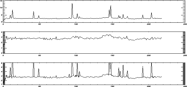
Figure E.1 shows the results of such a treatment. Figure E.1 (top) shows the values of a pixel of the camera as time elapses. The x-axis represents the frame number (time / integration time), and the y-axis is the signal in ADUs per second. These data were collected during a raster observation, and the satellite remained at the same position for about 20 frames, and the integration time was equal to 2.1s. A source is at the limit of detection (frames 135 to 150). All peaks are due to cosmic ray impacts. Figure E.1 (middle) shows the same data after the glitch suppression. The bottom panel shows both data and deglitched data overplotted. We see that the noise and the signal are not modified during this operation.
The method is robust and works for non-stabilised data. The only real
limitation is that we cannot detect glitches which last for a time
longer than or equal to ![]() . That means that the more frames we
have per camera configuration, the better the deglitching will
be. Some `special' glitches introduce a gain variation with a very
long time duration. These special glitches can be separated in two
types:
. That means that the more frames we
have per camera configuration, the better the deglitching will
be. Some `special' glitches introduce a gain variation with a very
long time duration. These special glitches can be separated in two
types: