

Next: 4.7 Spacecraft Pointing Jitter
Up: 4. Calibration and Performance
Previous: 4.5 Flat-Fields
Subsections
4.6 Point Spread Function (PSF)
4.6.1 Observed PSFs
Point source observations were performed with a  micro-scan raster with a step size of 3
 for 12
 pfov, and with a
  micro-scan raster with
step size of 2
 for the other pfov's, in order
to obtain a good spatial sampling of the PSFs. However,
due to the
undersampling of the PSF inherent to some CAM configurations, this did
not allow a fine enough sampling of the PSF for every optical
configuration. Therefore, users should be aware of this if
attempting to use a library PSF for deconvolution purposes.
The micro-scan raster used for the PSF measurements also yields
information about photometric variations as a function of the
position of the point source within a single generic pixel. The
raster spans several pixels, and the point source assumes a range of
positions with respect to the various pixels centres. If pixels are
assumed to be identical with respect to the variation of response
across their surfaces,
then the overall raster can be seen as building-up a set of PSFs
with families specific to particular relative positions of point
source and pixel centre (`sub-pixel positions').
Except for the 12
 pfov, one raster contains 9 sets
of 4 raster points with equivalent sub-pixel positions, within a
localised group of pixels. One PSF is constructed
by averaging these four point source images. This led, within the
detector region covered by each raster, to a set of 9 PSFs expressing
the appearance of a point source for each of the 9 particular sub-pixel
positions. Therefore, the PSF library contains one set of 9 PSFs for
each detector zone rastered for each configuration calibrated.
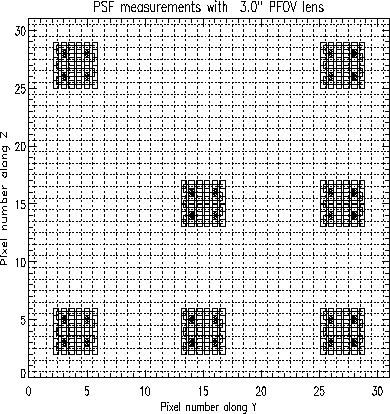
Figures 4.14 and
4.15 show examples of the micro-scans
performed for 3
 and 6
and 6
 pfov PSF
measurements.
All the rasters for a given optical configuration were done within one
observation time block, pointing on the same star.
Figure 4.14:
PSF measurements on different regions of the detector
for the 3
 pfov
pfov
|
|
Figure 4.15:
PSF measurements on different regions of the detector
for the 6
 pfov
pfov
|
|
All the PSFs of a given configuration are normalised by the flux of the
central PSF. This global normalisation
factor describes a photometric correction that would need to be
applied to point sources as a function of distance from the array
centre and/or as a function of source barycentre on the central pixel
of the point source. For each configuration, only one PSF is
normalised to 1. The normalisation factor is the integrated flux of
the reference PSF, excluding the edge pixels.
A detailed description
of the observations and analysis made can be found in the ISOCAM
PSF Report (Okumura 1998, [44]).
4.6.2 Model PSFs
In the optical PSF model computation, the pupil image is created in
Fourier space. The pixel size  in this space is given
by:
where  is the reference wavelength of the filter bandpass,
 is the square size of the applied image dimensions expressed by
the number of pixels and
  is the pixel size of the image in
the direct space in radians.
The diameter
  of the circular
aperture in Fourier space, in pixel units, is then given by dividing
the telescope diameter
  by the pixel size
  :
:
If  is expressed in
  m, its radius is given by:
 |
(4.2) |
In order to execute a correctly sampled computation both in Fourier
space and in direct space, it is necessary to create a finer sampling
and a larger image size than the real image coming from the ISOCAM
detectors.
If, in addition, one wants to add the detector pixel convolution
effect on the optical PSF model, then the sampling in
direct space should be better than at least half of the pixel size.
Once the image size is chosen, the central obscuration and the tripod
structure (supporting the secondary mirror of the telescope) are
added to the main aperture model. The Fourier transform of the
aperture then gives the optical PSF which will be convolved by the
detector pixel size and resized to the real dimension of the detector
array.
For more accurate models, one should integrate over the
bandpass profile of each filter multiplied by the spectral energy
distribution of the source. However, the theoretical and
monochromatic PSF constructed here, can be well compared with the
observed PSF as long as the bandpass is not too wide.
Thus, the model applied here neglects the impact of the
filter bandpass on the shape of the final PSF.
In Figures 4.16, Figure 4.17 and
Figure 4.18 the theoretical and the measured PSFs
are compared. Details are given in the ISOCAM PSF Report (Okumura
1998, [44]).
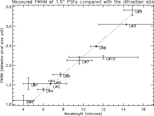
A comparison of the FWHM of the model
(Figure 4.17) and measured
PSF (Figure 4.18) to the Airy disk diameter of the
ISO telescope demonstrates that a good reproduction of the PSF is obtained
for all ISOCAM filters except for
LW10 and LW1. The deviation observed in LW10 could be an effect of the
very wide bandpass while the anomaly in LW1 is not yet understood.
Figure 4.16:
Comparison of the measured and the modelled PSF for the
LW9 filter and the 3
 pfov
pfov
|
|
Figure 4.17:
FWHMs of the modelled PSFs. The dashed line
is the Airy disk diameter (Section 2.1).
|
|
Figure 4.18:
FWHMs of the measured PSFs. The dashed line
is the Airy disk diameter (Section 2.1).
The horizontal bars indicate the bandwidth of each filter.
|
|


Next: 4.7 Spacecraft Pointing Jitter
Up: 4. Calibration and Performance
Previous: 4.5 Flat-Fields
ISO Handbook Volume II (CAM), Version 2.0, SAI/1999-057/Dc

