3.2.2) The PIA Measurement Buffer Control Window
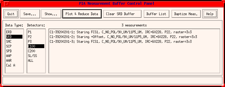
This Window serves to control the measurements in the buffers for selection and data handling. It opens via the "Process Buffers" menu item in the pull down menu "Buffers" by the PIA Top Window.

FIGURE 1: The PIA Measurement Buffer Control Window
Basically the window may be divided into three rows:
- The top line: It contains the menu buttons.
- The middle row: It contains selection boxes for the measurements and associated buttons, acting on them.
- The bottom line: It displays warning messages and other useful information.
The Top Line
It contains the following menu buttons:Quit
Closes the window.Note that the actual measurement data remain in the buffer and can be recalled at anytime by calling this window to pop-up again.
Save...
This pull down menu contains the menu item for saving the measurement to FITS file or IDL internal save file.FITS fileThis menu saves the selected measurement in the measurement list to a FITS file. It calls up the save file dialogue box giving the choice of saving the file to a different directory or under a different name.
Internal Save file
This menu saves the selected measurement in the measurement list to the IDL internal save file. It calls up the save file dialogue box given the choice of saving the file to a different directory or under a different name.
Show...
Header:This submenu originates from the fits header of the selected measurement. It is used also on every level for logging the processing steps which have already been performed. They are located at the end of the header and their lines begin with "PR...".
Compact Status:
This submenu displays the Compact Status File for the selected measurement.
Data Values:
This calls the PIA Show Structures facility (section 3.4.4) used to access all the variables corresponding to the selected measurement.
Plot and Reduce Data
This action button calls the main processing window for the selected measurement (ERD, ...).Clear ... Buffer
This action button helps to remove measurements of the selected data type from the buffer. A selection menu containing all the measurements corresponding to level and detector chosen pops up for the user to select all the measurements he/she does not want anymore to be on the buffer. Note that once your measurements are cleared from the buffer, they no longer exist and the only way to access them again is via reading from the external filesBuffer List
A text list of all measurements showed by this display is offered for saving and printing.Baptize Measurement
The user can give via this button a name to a measurement, which is then displayed on the far right part of the measurement's list. In this way he/she can eg better identify a measurement which was reduced in different ways than by the position within the buffer.Help
Calls the present page of the PIA User Manual.
The Middle Row
This row serves to control the measurements in the buffer. The selection boxes serve to select a measurement, the action buttons on the righthand side perform the actions on the selected measurement (or data type).Data Type:
This selection box offers the following various data types.
Type Description Pipeline Product PIA Product ERD: Edited Raw Data yes yes SRD: Signal per Ramp Data no yes SMD: Serendipity mode data no yes SCP: Signal per Chopper plateau data no yes SPD: Standard Processed Data yes yes AAP: Astro Physical Processed data no yes AAR: Automatic Analysis Result data yes no Cal A: Calibration A data yes no Note that the contents of the measurement box is updated depending on the data type selected.
Detectors:
This selection box offers the various detectors.Note that the contents of the measurement box is updated depending on the detector type selected.
Measurements:
This selection box displays the measurements according to the preselected data type and detector.The measurements displayed normally include various information in the FITS header and from the Compact status. The information is organized as follows:
The first field consists of the Detector followed by the '-', the TDT number of the observation, followed by the '-', the measurement number within this observation and then the ":", eg.
C1-01301305-1:The next field after the ':' character consists of the following information separated by the character ','For example,
- the Chopper mode
- the three wheel positions separated by the '/' character the Observation Mode
- the Object of the observation
- the AOT name
- the type of observation: pointing, tracking or raster and with the raster observation, it also displays the points per raster line and the number of lines, eg. raster=3x3
- the identification name for the measurement as given by the user (if any)
C1-05700101-2: Staring +Offset, C_NO_POL/60_UM/11P5_UM, IDS17504+6722, P22, pointing, Rectangular, "Mes1_without_degl"
Note that a measurement has to be selected explicitly by clicking on it with the mouse.
The Bottom Line
It displays the informative or warning messages.
| Date | Author | Description |
|---|---|---|
| 15/05/1996 | Martin Haas (MPIA) | First Version |
| 23/05/1996 | Wai-Ming Tai (DIAS) | Updated Version |
| 05/06/1997 | Carlos Gabriel (ESA-SAI) | Update (V6.3) |
| 15/10/1997 | Carlos Gabriel (ESA-SAI) | Update (V6.5) |