

Next: 4.2 Quality Check of
Up: 4. Data Processing
Previous: 4. Data Processing
4.1 Processing Overview
The ISO data for each instrument is processed automatically through a
pipeline (Off-Line Processing software or OLP) consisting of three stages:
Derive-ERD extracts the observation-relevant data from the telemetry
stream; Derive-SPD processes the
raw detector readouts into photocurrent and removes glitches due to
particle impacts; Auto-Analysis performs the astronomical calibration
of the data to produce a spectrum in flux units versus wavelength units.
The three separate stages were designed to allow observers
to choose at which stage to start their own reduction. For the three
scientifically validated LWS AOTs
it is expected that the final Auto-Analysis Results (AAR) product is
the starting point for reduction
(see Section 8),
but in some cases (see Chapter 6) an observer may
wish to start with SPD data and process this
to AAR through LWS interactive analysis (LIA -
see Section 8.2.3).
The files produced at each stage of the data processing are listed and
described in Chapter 7.
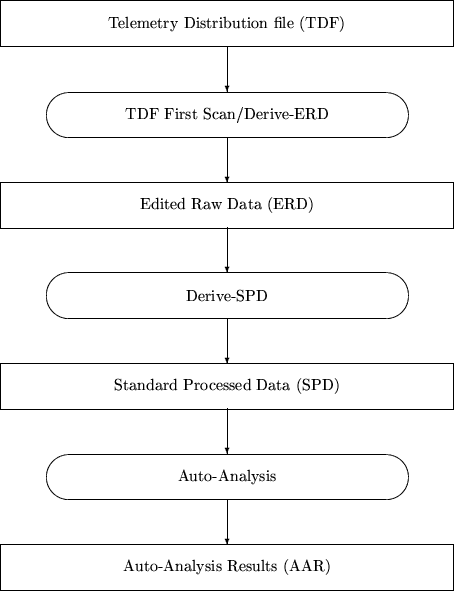
A global overview of the three
stages is given in Figure 4.1.
Figure 4.1:
Overview of the ISO data processing.
 |
The ISO processing is an automated process where the
end products (Edited Raw Data, Standard Processed Data and Auto-Analysis
Results) are quality checked (see Section 4.2). The
following is a brief overview of the three steps
in the processing. The algorithms used in the last two steps (Derive-SPD
and Auto-Analysis) are described in more detail in
Sections 4.3 and 4.4.
- TDF first scan/Derive-ERD
- The telemetry data from the satellite is
transmitted to the Ground Station in blocks called `formats', each format
containing the data for a 2 second period.
These data are stored in the Ground Segment as so-called Telemetry
Distribution Files (TDFs). The TDFs contain the raw scientific data from
the Prime Instrument and satellite and instrument housekeeping information
for a complete revolution. They are, thus, the prime input for the ISO
data processing system. The first step in the ISO processing for an
observation is to extract from a TDF the raw data relevant to that
observation. This is carried out in two stages:
- `TDF first scan' reads the TDF (and other ancillary files) to
create a set of pointers to relevent events in the observation,
such as: the start and end of the observation, the start and end
of LWS illuminator flashes, the start and end of mechanism
(grating or FP) scans. This is stored in the `Compact Status
History' (LSTA) file.
- Using the Compact Status History, `Derive-ERD' extracts the
information for the observation into the set of Edited Raw Data (ERD)
files for the observation. The data extracted includes the instrument
science data, instrument housekeeping data and relevent satellite
information (e.g housekeeping, pointing and orbital information).
The ERD produced is a complete set of the data required to process an
observation, but, as no conversion from engineering values has been
made, it requires a detailed knowledge of the instrument to
process and is therefore not recommended as a starting point.
- Derive-SPD (SPL)
- In the second stage of the ISO data processing
most of the instrument specific peculiarities are removed and some
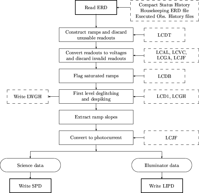
basic calibrations are performed. In Figure 4.2
a schematic overview of the Derive-SPD process is given.
Figure 4.2:
Schematic overview of
Derive-SPD. The names in the dashed boxes indicate auxiliary
or calibration files.
 |
The output of this process (Standard Processed Data or SPD) contains
only scientific data, still in engineering units
(i.e. not wavelength or flux calibrated), and in chronological order.
Derive-SPD processes a Target Dedicated Time (TDT) which can consist
of more than one AOT. The individual data types (i.e. different AOTs
or subsystems in the instrument) can be identified using
LWS Compact Status History. This file is produced by TDF
first scan. Derive-SPD processes the raw detector readouts into
photocurrent by fitting the raw data ramps. It also removes glitches
due to particle impacts. Derive-SPD also processes the measurements
of the internal illuminators into a calibration file that is used by
Auto-Analysis.
- Auto-Analysis (AAL)
- This final stage in the ISO processing
performs all the astronomical calibrations of the data.
The main output of this stage is the LSAN file,
containing the flux and wavelength calibrated spectrum for a single AOT.
The AAL process corrects for the spectral responsivity (absolute
responsivity and responsivity drift), removes the dark
current, performs the wavelength
and the flux calibrations, including the correction for the spectral
resolution element (or spectral bandwidth).
Three new files are produced by Auto-Analysis.
A schematic overview of the Auto-Analysis process is given in
Figure 4.3.
Figure 4.3:
Overview of Auto-Analysis.
The files in dashed boxes are the calibration files used by AA.
|
|
Auto-Analysis does not include:
- averaging of repeated spectral scans
- joining together of spectra on adjacent detectors
- generation of maps for raster scans
- subtraction of the local astronomical background
- correction for the effective aperture of an extended source


Next: 4.2 Quality Check of
Up: 4. Data Processing
Previous: 4. Data Processing
ISO Handbook Volume III (LWS), Version 2.1, SAI/1999-057/Dc


![\resizebox {15cm}{!}{\includegraphics[20,140][470,774]{aa_overview.ps}}](img138.gif)