|
The ISO spacecraft was designed around a large cryo vacuum vessel (cryostat) -- effectively a very large thermos flask -- cooled by the evaporation of super-fluid helium to an extremely low temperature. Figure 3.3 shows the general configuration of the cryostat. The cryostat provided an extremely cold stable environment for the ISO telescope, instruments and instrument detectors. This low temperature was required by the scientific instruments in order to obtain the extremely high degree of sensitivity; without this, the detectors (in combination with their electronics and the observing methods used) would only have been able to detect the thermal emissions of the spacecraft, telescope and detectors themselves. The original requirements on the cryostat (later on fulfilled) are given in Table 3.1.
Cryostats are not the only means available for cooling scientific instruments. They carry a significant mass penalty due to their large and heavy construction, they have the drawbacks in the need for complicated ground handling procedures, have difficult launcher interface problems and a lifetime limited by the capacity of the cryogen storage tanks. However, cryostats are capable of providing a significantly more stable environment than the alternatives and this was the driving requirement for the ISO mission.
The cryostat surrounded the telescope and scientific instruments with a vacuum vessel, with cooled shields built into the vacuum vessel walls. A diagram of this can be seen in Figure 3.3. Inside these walls a toroidal tank containing up to 2300 liters of super-fluid helium surrounded the optical axis of the telescope including the telescope itself. At the `top' of the cryo vacuum vessel, a cryo cover protected the thermal equilibrium of the cryostat and prevented atmospheric condensation inside the cold telescope until after the launch, at which time it was jettisoned.
The tank was insulated from external heat inputs by three Vapour-Cooled radiation Shields (VCS) equipped with Multi-Layer Insulation (MLI). The tank, radiation shields and telescope were suspended from the Cryo Vacuum Vessel (CVV) by low-conductivity straps. Cooling through the cryostat was achieved in different ways, depending on the subsystem requirements. The Optical Support Structure (OSS) and main baffle were cooled by cold helium gas, resulting in a 3.2 K temperature. The primary mirror was cooled through thermal straps to the OSS, and the seconday mirror was cooled by means of copper braids connecting it to the OSS. The instruments and detectors were either cooled by cooling straps connecting them to the OSS (giving them a temperature of 3.2 K) or by direct cooling straps connection to the helium tank, leading to 2 K temperatures. This is discussed in the ISO telescope Design Specification document, [90] and Ximénez de Ferrán 1995, [167]. A heat shield connected to the OSS enclosed all four focal-plane units and provided a light-tight environment.
The pressure inside the helium tank was 17 mbar, the equilibrium boiling point at a temperature of 1.8 K. This pressure was maintained in orbit by the impedance of the vent line, and on the ground prior to launch by continuous pumping of the tank exhaust. The gaseous-helium exit was located at the highest point of the tank, allowing separation by gravity of the liquid and gas phases during ground operations. Once in orbit, one of the remarkable properties of superfluid helium was exploited, the so-called `thermodynamic fountain effect', by which a simple porous plug functions as a phase separator, keeping the liquid phase in the tank while allowing the gaseous helium to flow through the vent line. The vent lines were arranged so as not to impart a thrust to the satellite.
After the main helium tank had been topped-off, approximately 72-48 hours before launch, it was not possible to access the Ariane's payload in order to pump the cooling system from an external source. In addition, the cryostat's main helium tank was closed at this point resulting in a cessation of helium venting through the Vapour-Cooled radiation Shields (VCS). As the VCS could not be left without active cooling for such a period, it was necessary to provide another source of coolant for the VCS prior to launch. Adjacent to the cryostat cover was a smaller auxiliary tank containing 60 liters of normal liquid helium. This was used to vent cooling helium through the VCS and maintain the thermal equilibrium of the VCS until immediately before launch at which time the auxiliary tank was completely emptied. It had no further function.
During the launch of ISO, commands issued by Ariane's electronics operated a set of cryogenic valves that opened the helium vent line, the main helium tank and its porous-plug phase separator to space. Initially, the vented helium mass flow rate was about 20 mg/s, rising to a peak of about 27 mg/s and then falling until, after about 20 days in orbit, it reached its in-orbit equilibrium point of 5 mg/s.
To cope with this range of flow rates the system was equipped with two sets of nozzles. Initially, both were opened to accommodate the high mass flow rate. As the rate fell and the temperatures decreased the larger nozzles were closed, leaving only the smaller set open (see Figure 3.4).
The ISO telescope was a 60cm diameter aplanatic
Richey-Chrétien system with an overall focal ratio of f/15. The main
feature of this type of telescopes is the absence of coma and spherical
aberration,
leading to a larger field of view than the classical Cassegrain type. The
optical quality of the primary and secondary mirrors provided diffraction
limited performance at wavelengths beyond 5![]() m, also limited by
pointing
performance (Section 5.4.1). As already mentioned,
stringent control of straylight
was accomplished by a sunshade, the Cassegrain and
main baffles and additional light-tight shields around
instruments, as well as by imposition of viewing constraints (see
Section 4.1). Figure 3.3 shows the
configuration of the ISO optical subsystem within the cryostat and Figure
3.5 shows an expanded view of the telescope assembly.
m, also limited by
pointing
performance (Section 5.4.1). As already mentioned,
stringent control of straylight
was accomplished by a sunshade, the Cassegrain and
main baffles and additional light-tight shields around
instruments, as well as by imposition of viewing constraints (see
Section 4.1). Figure 3.3 shows the
configuration of the ISO optical subsystem within the cryostat and Figure
3.5 shows an expanded view of the telescope assembly.
The optically used diameter of the primary mirror is 634 mm, but the
entrance
pupil is defined by the secondary mirror which imposes the effective
aperture
of 600 mm. The central obscuration is imposed by the largest element
centered
on the optical axis, which is the largest part of the secondary baffle
diameter. The tripod is mounted at 0![]() , 120
, 120![]() , 240
, 240![]() from the
negative side of Z axis. Adjustment devices (with 5 degrees of freedom)
on the
secondary mirror were necessary to perform the internal alignment of the
telescope, completed during ground tests.
from the
negative side of Z axis. Adjustment devices (with 5 degrees of freedom)
on the
secondary mirror were necessary to perform the internal alignment of the
telescope, completed during ground tests.
Information on the mirrors is given in Table 3.2.
| Object | Value |
| Primary mirror (M1) | |
| Total diameter | 640 mm |
| Optically used outer diameter | 634 mm |
| Diameter of central hole | 145 mm |
| Optically not used inner diameter | 150 mm |
| Radius of curvature | 2000 mm |
| Conic constant | |
| Secondary mirror (M2) | |
| Optically used outer diameter | 87.6 mm |
| Diameter of central hole | 15 mm |
| Optically not used inner diameter | 25 mm |
| Radius of curvature | |
| Conic constant | |
| Telescope | |
| Focal length | 9000 |
| Numerical aperture | f/15 |
| Axial mirror separation | 854 |
| Entrance pupil | 600 mm at 5849.3 mm behind M1 |
| Exit pupil | 87.6 mm at M2 |
| Secondary baffle maximum diameter | 173.9 mm at 742.4 mm before M1 |
| Tripod width | 20 mm |
| Linear obscuration (central + tripod) | 0.36 |
| Instrument field of view | 8.5 |
| Unvignetted field of view | 3 |
| Pyramidal mirror tilt | 44.515 |
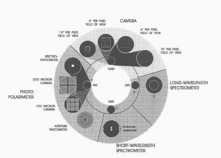
A part of the 20![]() unvignetted field of view of the
telescope (see Figure 3.6)
was distributed into the entrance pupil of each
of the four instruments by a pyramidal mirror located on the telescope
axis. This resulted in a 3
unvignetted field of view of the
telescope (see Figure 3.6)
was distributed into the entrance pupil of each
of the four instruments by a pyramidal mirror located on the telescope
axis. This resulted in a 3![]() unvignetted
field of view for each instrument at an angle of 8.5
unvignetted
field of view for each instrument at an angle of 8.5![]() from the
telescope optical axis, with the QSS aligned
with this axis. The four instruments fields of view were centered
around this axis. Since the four instruments viewed separates areas of the
sky, switching an astronomical target between instruments required a
repointing of the satellite. Figure 3.6 shows
schematically how the individual apertures were used by the instruments.
from the
telescope optical axis, with the QSS aligned
with this axis. The four instruments fields of view were centered
around this axis. Since the four instruments viewed separates areas of the
sky, switching an astronomical target between instruments required a
repointing of the satellite. Figure 3.6 shows
schematically how the individual apertures were used by the instruments.
The exact positions of all the apertures with respect to the QSS are given in the ISO Focal Plane Geometry data file (IFPG ), see Section D.11, and are reproduced in Table 3.3.
| Instrument | Y coordinates | Z coordinates |
| QSS ref. | +0.000000 | +0.000000 |
| CAM | +8.544170 | +0.124167 |
| LWS | +0.225000 | |
| PHT1 / PHT-P | +8.435000 | |
| PHT2 / PHT-C | +8.435000 | |
| PHT3 / PHT-S | +8.415000 | |
| SWS1 | +1.173330 | |
| SWS2 | ||
| SWS3 | ||
| SWS4 |
The main elements of the AOCS are presented in Figure 3.7, which also shows the ISO spacecraft axes.
The Quadrant Star Sensor (QSS) was aligned with the ISO telescope optical axis. The boresight of the QSS defined the x-axis of the ISO body coordinate system. The z-axis was defined by the Fine Sun Sensor (FSS), which provided control about the x-axis during pointings and about the x- and y-axis during slews. The Star-Tracker (STR), located outside the cryostat, provided two axis control about the y- and z-axis during pointings by the tracking of a single guide star. Slews were controlled by gyroscopes.
The ISO attitude was constrained to limit heat input to the cryostat and
straylight into the telescope. The Sun constraint was that the line of
sight of the +x-axis must be within
![]() of the Sun direction and the Sun vector must not be rotated
by more than
of the Sun direction and the Sun vector must not be rotated
by more than ![]() around the x-axis from the +z half-plane of the
satellite x-z plane. This was monitored by the FSS. The Earth constraint
constrained the aspect angle between the x-axis and the Earth in a
non-linear manner. This was monitored by the Earth Limb Sensor (ELS).
Other constraints were related to the Moon and Jupiter
(see Section 4.1).
around the x-axis from the +z half-plane of the
satellite x-z plane. This was monitored by the FSS. The Earth constraint
constrained the aspect angle between the x-axis and the Earth in a
non-linear manner. This was monitored by the Earth Limb Sensor (ELS).
Other constraints were related to the Moon and Jupiter
(see Section 4.1).
| Quadrant Star Sensor (QSS) | |
| Field of View |
|
| Sensitivity |
|
| Fine Sun Sensor (FSS) | |
| Field of View |
|
| Accuracy about x-axis | |
| Accuracy about y-axis | |
| Noise Equivalent Angle | 2
|
| Star-Tracker (STR) | |
| Field of View |
|
| Sensitivity |
|
| Bias error | 2
|
| Tracking speed | 5
|
The AOCS elements were found to meet the specifications, summarised in Table 3.4. A more detailed description of the AOCS system can be found in Batten & Stephenson 1998, [9].
ISO was operated in a similar manner to a ground-based observatory, and
therefore the spacecraft had to be able to manoeuvre smoothly from one
celestial source to the next, and then maintain accurate pointing on that
target. The spacecraft had also to be capable of pointing at any region of
the sky
that satisfied the straylight constraints. The slew speed between sights was
set at 7![]() /min in order to optimise observation time, and the
duration of
each observation ranged from a few seconds to up to 10h, depending on the
type of source.
/min in order to optimise observation time, and the
duration of
each observation ranged from a few seconds to up to 10h, depending on the
type of source.
The pointing requirements were satisfied by the spacecraft's Attitude and Orbit Control Subsystem (AOCS), in combination with careful spacecraft structural design, to avoid thermo-elastic deformation between the telescope's optical axis and the attitude sensors. Four operational pointing modes were defined:
For the high-accuracy pointing modes, the attitude errors were measured with gyroscopes, a Star-Tracker and the Fine Sun Sensors. In the calibration mode (activated nominally once per orbit), the Quadrant Star Sensor replaced the Star-Tracker.
A state-reconstructor in the AOCS computer produced minimum-variance estimates for the attitude, angular velocity and disturbance acceleration. This state-reconstructor also served as a sensor-data smoothing filter.
The control torques for high-performance slews and pointing modes were
provided by a reaction-control wheel system, giving a maximum torque
of 0.2Nm, with a
total of 126 torque levels, and a maximum angular-momentum storage
capability of some 18Nms. A so-called `dual control law' was used
together with a velocity
controller that limited angular velocities to 8![]() /min. The
`dual control law' consisted of a non-linear time-optimal subcontroller
and a linear state feedback
subcontroller. For large errors during slewing, the time-optimal control
prevails, whereas for fine pointing, the linear law predominates.
/min. The
`dual control law' consisted of a non-linear time-optimal subcontroller
and a linear state feedback
subcontroller. For large errors during slewing, the time-optimal control
prevails, whereas for fine pointing, the linear law predominates.
An important factor in achieving the requisite pointing accuracy for the ISO spacecraft was the limiting of the drift between the optical axis of the telescope and that of the Star-Tracker. Such drift can be induced by transient thermo-elastic deformations of structural elements linking the two optical axes. Consequently, the Star-Tracker support structure was mounted on the cryostat's outer wall, rather than on the Service Module. This alone does not prevent local deformation due to temperature gradients in the cryo vacuum vessel from degrading pointing performance. It is also necessary to maintain a stable and uniform temperature distribution in these two structures.
This temperature stability was achieved by covering the cryo vacuum vessel
with
multi-layer insulation (MLI), even at the expense of a small penalty in the
lifetime
of the satellite. In addition, the Star-Tracker sensors (two for redundancy)
were enclosed within a thermal housing, with heaters, which provided a
constant sensor temperature and, even more importantly, maintained a
constant
temperature gradient between the mounting feet of the operational
Star-Tracker (better than 0.1![]() C over one orbit, except for
2h around perigee).
The specially stiffened fixing of the housing to the cryo vacuum vessel
ensured that the thermal conductance between the two was less than
3mW/
C over one orbit, except for
2h around perigee).
The specially stiffened fixing of the housing to the cryo vacuum vessel
ensured that the thermal conductance between the two was less than
3mW/![]() C.
C.
The in-orbit performance of the AOCS system and the final pointing accuracies are given in Section 5.4.1.