

Next: 4.11 Astrometric Uncertainties
Up: 4. Calibration and Performance
Previous: 4.9 Ghosts and Straylight
4.10 Field of View Distortion
ISOCAM images suffer from a field distortion caused by optical
elements like the field mirror, filter and lens. Each of these
elements acts in a different way and to a different extent. The
inclination of the Fabry field mirror causes a trapezoidal
deformation observed in the distortion pattern. This effect is
reproduced in a simple first order optical computation. Pincushion
distortion occurs when the beam passes through the lens and is caused
by the aspherical aberration of the lens. In this case, first order
computation is not sufficient to account for the effect. The width of
the filter plates contribute also in a magnification change. As the
beam is converging when passing through the filter, the parallel
planes of the filter plates (whether inclined or not) have an
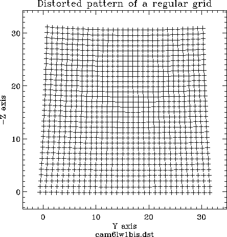
influence on the field pattern on the detector. An example of a field
distortion pattern derived from a raster observation through the
6
 pfov lens with the LW1 filter is shown in
Figure4.26.
It is important to correct data for this instrumental effect,
especially when making a coadded map from a raster observation and
also when improved astrometry is needed.
The correction is made by means of a pair of polynomials which relate
the distorted two-dimensional space to a distortion-free
two-dimensional space.
Figure 4.26:
A typical field
distortion pattern derived from a raster observation
through the 6
 pfov lens with the LW1
filter
|
|
The distortion is weak through the 1.5
 pfov lens
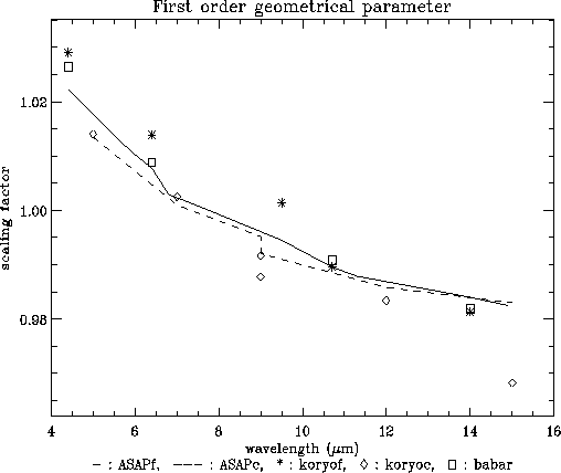
and becomes stronger for larger pfov's. The field distortion also
depends on the filter. Figure 4.27 shows the
wavelength dependency seen in the data by means of the magnification
parameter derived from the linear terms of the fit polynomials.
The field distortion correction includes polynomial coefficient sets
for the different filters. There are two types of coefficients. One
derived from measurements and the other from a ray-tracing optical
model which was optimised to fit the observations. Measurements on
real data are possible in the case of the 6
 and 12
 pfov lenses. The distortion measurement through the
3
 pfov lens was difficult because the effect
which had to be measured was of the order of the accuracy of
the point source position determination routine. The
distortion amplitude is even smaller through the
1.5
 lens, and is therefore impossible to measure in
the real data.
In CIA the distortion polynomial coefficients are available in a
CAL-G file called `clwdisto_*.fits'.
For the ISOCAM configurations for which no accurate measurement was
possible or for which no data are available, the coefficients are
derived from the optical model. A more detailed discussion on
this subject can be found in the ISOCAM Field Distortion Report
(Okumura 2000, [46]).
Figure 4.27:
Scaling factor of the distortion correction polynomials with respect to the
detector centre.  : filters (from ghost measurements),
 : CVFs (from ghost measurements),
  : new
data sets. Solid line: filters model; dashed line: CVFs
model (Okumura 2000, [46]).
|
|


Next: 4.11 Astrometric Uncertainties
Up: 4. Calibration and Performance
Previous: 4.9 Ghosts and Straylight
ISO Handbook Volume II (CAM), Version 2.0, SAI/1999-057/Dc


