|
The 12 detectors of each grating detector block must be individually calibrated such that the resulting spectra from each detector within a block gives the same signal. This step has been dubbed `flat-fielding' for SWS. In general, the signal to flux calibration per detector should formally account for flat-fielding. However, the variations of an individual detector relative to the average of the detectors can be easily measured from any science observation and not just from the photometric calibration observations. This approach makes use of the entire SWS database of observations to determine the flat-field coefficients.

|
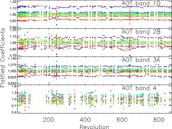
The calibration of the flat-field is determined from dark subtracted, relative spectral response and photometric gain corrected data of roughly 1000 observations throughout the ISO mission. The average response of each detector in the band is measured against the average response of all the detectors combined. Figure 5.29 shows the flat-field coefficient for bands 1D, 2B, 3A, and 4 throughout the ISO Mission, for sources brighter than 50 Jy (100 in band 4) and median filtered over time for clarity of the trends. Because of the constancy of the flat-fielding, a specific calibration can be applied to correct it. These values are contained in the Cal-G 43 file.
The application of a separate flat-fielding step aids in removing some of the ambiguity of applying an OFFSET or GAIN flat-fielding correction in post processing. The flat-fielding is always a gain correction in the standard processing. In post processing it might be necessary to account for offsets introduced through the dark current application. There remain cases when it is still preferred to apply a flat-fielding correction in post processing, since effects like satellite pointing can also change the flat-fielding. However, the corrections will be smaller.
In Figure 5.29, there are two revolutions which show significantly different flat-field coefficients, these occur at revolutions 244 and 641. In both of these revolutions, a pointing experiment was performed which places and object at a series of different positions within the SWS apertures. From these data, it is clear that mis-pointings will have a significant effect on the flat-fielding.